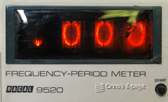
Racal 9520 Frequency Period Meter
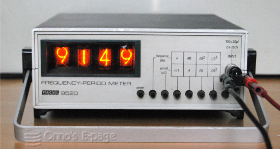
The Racal 9520 is a British made 4-digit TTL based
frequency counter with nixie tube display.
Its manufacturer calls it a frequency and period meter.
After all, counting is the way, measuring frequency is the goal.
In 2012 this counter was offered on a Dutch internet
auction site.
It was sold as not functional.
I decided to take the chance, after having verified that
this was a nixie counter indeed.
This is a basic counter, only having 4 digits.
It can measure either frequency or period times in
four ranges:
- x1, x10 ,x100 ,x1000 Hz
- x0,1, x1, x10, x100 μs
The test button delivers a 1000 Hz signal derived from
the internal frequency reference to the counter.
Racal was a British manufacturer of radio and
electronic measurement equipment.
They are well known for their receivers and transmitters.
In the 1980'ies, they also made modems and other networking
stuff.
It wasn't very easy to date this counter.
I couldn't find a downloadable service manual.
Some sites do list copies of the manual for sale.
One of these sites mentioned 1970 as the year this model was
introduced.
Only one of the IC's had an intelligible production code,
pointing at 1970 as the production year.
The case has the form of a metal sleeve slid around the chassis.
The mains cord is attached.
The carrying handle can be used as tilt support.
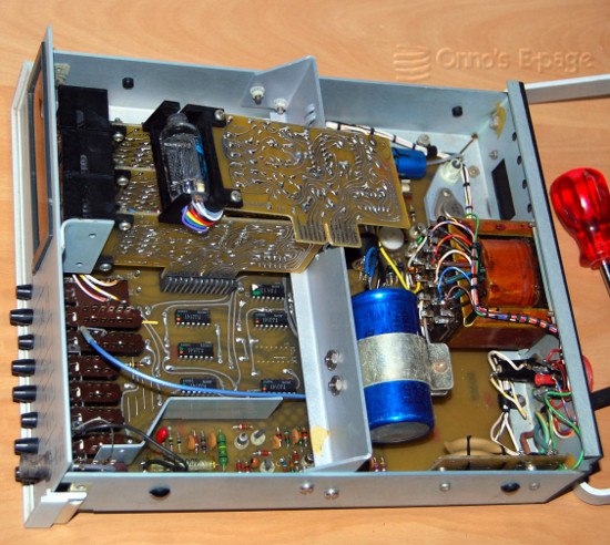
Most of the electronic circuits are built on circuit boards,
except for the mains transformer and the power supply electrolytic,
that are mounted on the metal frame that holds the main board.
A row of push buttons on the main board, accessible from the
front panel is used to switch the device on and off
and to select functions and range.
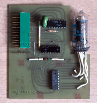
The four nixie tubes are each on a separate counter module board.
Each of the counter modules contains:
- 1 ITT GN13A nixie tube,
- 1 FJJ131 (7490) decade counter,
- 1 FJH141 (7400) quad NAND port,
- 10 ZTH342 transistors to drive the cathodes,
- A BC109 transistor, a silicon diode and some resistors.
Most of the circuitry is on the main circuit board.
It contains the power supply, crystal oscillator,
control ciruitry, push-button switches and input amplifiers
After some checks, I switched the counter on.
The display came up.
It showed three zeroes while the leftmost nixie only
showed a few shimmering spots.
The “test” button gave a reading of
1000,0100,0010 or 0001 depending on the range set.
I pulled the leftmost counter module to test the nixie.
Using my HV power supply, probing the cathodes,
I tried to light the digits.
But I was't able to get a better digit.
So it really was the nixie tube that was bad.
I dug in my nixie stuff box to look for a suitable replacement, but found none, initially.
The GN13A has 16.5 mm digits, while the largest side view nixies that I
had on stock, had 14 or 15.5 mm digits.
Finally, digging deeper I found a small circuit board with a suitable nixie.
This was a single counter module I had once
bought on an electronics flea market.
This one carried an ITT GNY17 nixie, that has 16.5 mm digits and a
hexagonal anode mesh, like the GN13A.
At first, I suspected it would be faulty as the tip of the
tube was broken, but it still worked.
Brilliant!
I unsoldered the nixie, extended its wires and soldered it onto
the Racal counter module.
While I was at it, I removed the dead spider and its web
and cleaned the display window.
Then I inserted the module and tried it... Perfect!
Well, almost, as the digits in this nixie are
placed slightly higher in the tube.
You can't have it all...
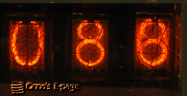
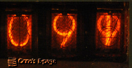
After the counter had warmed up a bit,
I noticed the rightmost nixie had a problem displaying digits
“8” and “9” correctly.
They were mixed with “0” and “1”
respectively.
This had to be a decoder failure.
Apperently the driver transistor for the
0 or 1 was activated together with 8 or 9, respectively.
I traced the circuits on the counter module and was able
to draw a rough schematic and understand how it worked.
Here, the BC109 transistor is used as an inverter that turns off the
“0” and “1” when one of the B,C or D
outputs of the FJJ131 (7490) counter are logical “1”.
I measured the inputs for the BC109 and found that the silicon
diode on this counter module had a suspiciously high threshold voltage,
further increasing as it warmed up.
I replaced the diode and tried.
Perfect!
Finally, I compared the readings of this counter with the
Monsanto 101B.
They were equal within one count.
Apparently, the fragile crystal in its glass case hadn't
suffered.