RJ-45 cable tester
Though a cable tester is actually a simple device,
it can save you a lot of time compared to using an
ohmmeter and a test load at the other end of the cable.
I stubbornly decided to make one myself, though very cheap testers
can be bought nowadays.
This cable tester can test continuity and short circuits in wall cabling
and patch cords that have RJ-45 connectors.
It consists of two units:
- A battery-powered sequence generator to connect to one end,
- A read-out box with 8 LEDs to connect to the other end of the cable.
Two units are needed to perform and end-to-end check of the cable and
assess continuity of all 8 wires individually.
In the autumn of 2007 I was replacing all the old phone wiring in my house by
Cat5E cabling, suitable for Gbit Ethernet networks.
I tried the cabling by connecting my laptop and my network router.
Unfortunately, a few cable runs did not work, and I could not find out why.
At this time, I also had a few unreliable Ethernet connection cables.
In order to be able to properly test the cables, I wanted to build a
cable tester.
Of course, it would be cool to do a reflection test to localise shorts
or subtle cable faults, but most cable problems are simple continuity
problems that can be tested more easily using a continuity tester.
I decided that I needed a circuit that connects a voltage to one of the wires
at one end and a display unit that shows which wires are selected at the other end.
Perhaps I could think of a solution where I could have the display unit at the
same end as the sequencer, but then I would have to connect some kind of terminator
at the other end.
I could not think of a way to test the cable without walking from one end to
the other to connect my testing gear.
The bottom line is, if you want to do an end-to-end test, you will
have to be at both ends.
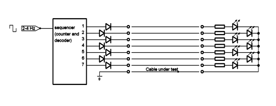
I came up with a circuit using 7 LEDs at one end, using one of the wires
as a return (“-”) wire.
That left me with a problem: what if the return wire is interrupted or non-existent?
It is not enough to know that the return wire is interrupted, as the cable
can have more than one fault.
I thought of a few ways to split the test in two, using different return wires.
But I found that unelegant.
I almost went to buy a simple cable tester.
Today, you can buy one for less than 10 Euros. But no.
I wanted to build one myself.
Then decided to google a moment for other cable tester designs.
On
SB projects
I found a circuit that was very similar to mine, designed by San.
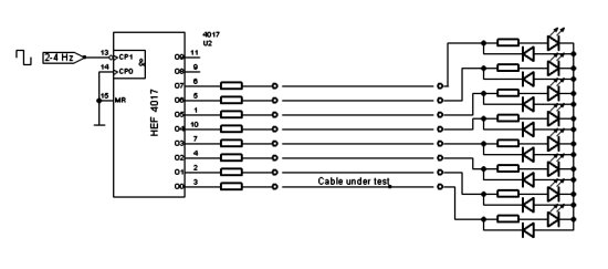
He had found an elegant solution to the return wire problem: he used all of the unused
wires as a return, putting them in parallel.
I thought of ways to improve the circuit, but decided to hurry up and build it.
After all, I had a cabling problem waiting.
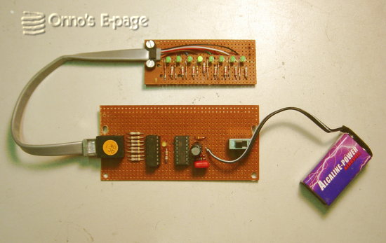
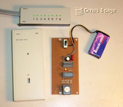
I used a small plastic case for the display unit.
On a piece of perfboard, I mounted 8 green high-efficiency LEDs, looking
through 8 holes in the case.
In order to fit the display unit in a very flat case,
I did not put an RJ-45 receptacle in it.
Instead, a piece of flat UTP cable is protruding from the box, with a
male RJ-45 connector at the end.
The sequencer is housed in a slightly larger box.
It contains an oscillator circuit and a 4017 decimal counter-decoder.
Every pin of the RJ45 connector is connected to one of the outputs
of the 4017 decoder through a resistor, allowing the 4017 to
sequence the pins.
The display unit can be connected to the sequencer directly.
A piece of RJ-45 cable and a female-female connector are needed to complete
the test set and test wall cables as well as patch cables.
The tester is really easy to use.
Connect the sequencer to one end and the display unit to the other end.
If everything is OK, you'll see all 8 LEDs blink sequentially.
If one LED remains dark there is an interruption.
If two LEDs light simultaneously, there is a short
(by the way: in case of a short, the LEDs
have to share the current so they are dimmer than normal).
If the LEDs light out of order, two or more wires have been swapped.
There is always a small pause (during 2 of the 10 counts of the sequencer,
no wire is activated) so you can determine which is the first one in the
sequence (the first one after the pause).