Guitar amplifier (pre-amplifier)
After getting the
power amplifier to work, it took me
a few months to get started with the pre-amplifier.
Building it took more time than I expected.
Actually, it is quite a complex amplifier.
First, I spent a few evenings to plan and design
the lay-out.
Joining the assembled pre-amplifier to the power amp
took some more time.
Then, final check, power-up and test...

The design
The intricate pre-amplifier is one of the reasons why I
chose the VOX AC15 as an example.
It actually contains two pre-amplifiers, each connected
to one of the inputs of the power amplifier.
First, there is the “clean” channel consisting
of a single EF86 AF penthode.
This stage should give a clear and bright sound.
The other channel is the tremolo/vibrato channel.
First I thought: tremelo, ok, but vibrato?
After all, tremolo is rapidly changing volume
of the signal. Many guitar amps contain tremolo units.
But vibrato, changing the pitch of the instrument?
I studied the circuit to see what is happening.
On the right, there is a VLF phase shift oscillator that
produces the driving signal for tremolo/vibrato.
The first stage is easy: just a triode amplifier.
After the input stage, there is a paraphase stage,
producing two opposite output signals.
The outputs are connected to two filter stages, each with two inputs,
having different time constants.
The phase shift of these filters with the
180 degrees phase shift of the paraphase stage will
produce interesting results when adding both signals.
I expect a kind of comb filter will result.
The third stage is a mixer controlled by
two opposite signals from a paraphase splitter that
is connected to the VLF oscillator.
The controlled mixer stage switches between two differently
phase shifted signals and some frequencies will be cancelled
when the signals are equally strong.
This may resemble a vibrato.
A switch labeled “vibrato on/off”
cancels one half of the mixer stage, which
leaves the tremelo but takes away the phasing and comb filter.
After the mixer there is a 5-stage high pass filter to
filter out the VLF driving signal.
I am very curious how this will sound.
It must be good, it is one of the reasons why people
love the AC15.
The tremelo unit has a “depth” trimpot that
is hidden inside.
I decided to move it to the front panel.
We'll find out if this is a useful control.
My son inquired whether the amplifier would deliver
groovy distortion. To produce more distortion, I decided
to add some more positions to the “brigh”
and cascade the two pre-amplifiers, so there is a
lot of extra gain, controlled by the volume control
of the “clean” channel.
We'll hear what that sounds like.
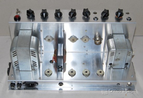
Originally, all four inputs are at the left of the
front panel.
I decided to make some changes to the front panel
lay-out to group the inputs and controls per channel.
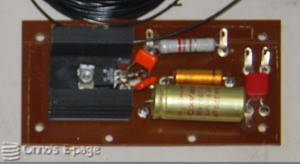
Finally, I designed the DC power supply for the
heaters of the pre-amplifier valves.
The power transformer has a 36 V winding
that was originally intended to power the heaters of
two 12AX7 valves.
I put the EF86 in series with the 12AX7 and 12AT7,
adding 6.3 V to the heater string.
Because the EF86 needs 200 mA, the two 12.6 V
valves need a bypass resistor of 250 Ω.
I used a 12V regulator to control the voltage for
the 12AX7, thus regulating the current through the
other two valves.
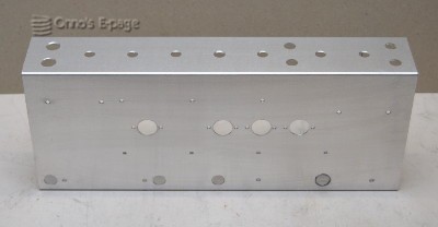
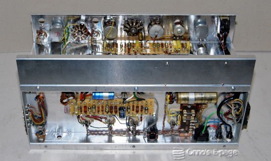
Building up the pre-amp
I had a u-shaped chassis made from 1.5 mm aluminium
sheet.
I drilled the holes and removed the burrs.
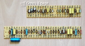
Then I populated the two tagboards and the DC heater
power supply.
I collected all the pots and rotary switches and
trimmed the shafts to size.
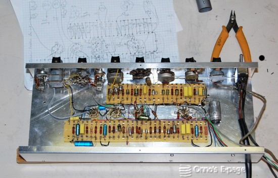
I mounted the four valve sockets and the two
tagboards. Then I started to add the power and
ground wires.
I tied the wires together in a cable harness.
Then I mounted the inputs and controls and
soldered the remaining components in place.
I checked the wiring against the circuit diagram
and admired my work.
Putting it together
Now was the time to join the pre-amplifier chassis
to the
power amplifier
chassis.
I threaded the power wires and signal input leads
from the power amp
through the holes in the chassis and soldered them
to the pre-amplifier circuits.
I extended the two wires from the 36 V winding
and soldered them to the heater supply board.
Added the wiring for the high-cut control and
the power switch and pilot light.
Then I tied the wires together in a cable harness.
It was time to
power up and test.