Guitar amplifier (first try)
This is my first attempt to build a guitar amplifier
inspired by the VOX AC15 design.
One might call this the “Dutch prototype”,
as it is using vintage Amroh transformers.
Although in the end I had to conclude that I had built an amplifier
that was straining regular EL84 valves a bit too much, I was quite
satisfied with its performance.
I continued and
built a neater and cooler running output amplifier
using a set of Geloso transformers.
But first about this one.

The Plan
One day my son told me he wanted to play the electric guitar.
I enthousiastically proffered to build a real groovy
sounding valve based amplifier for him.
I decided to aim at an output power of 10-15 W.
That should suffice for practice purposes and small performances,
though it may perhaps already exceed the neighbours' tolerance
for musical practice sound levels.
I looked around the preferences of guitar players towards amplifiers,
and found many push-pull amplifiers using EL84 penthodes.
Of these, the VOX AC15 is generally praised by many,
so this amp would become my example.
The design is from 1960, it has a cathode biased push-pull output
stage and an intricate pre-amplifier section.
Collecting the components
I didn't have any suitable transformers at hand,
so I looked around on the Internet.
I found a few smaller push-pull output transformers, one for
EL36, one for EL81 and one for EL84.
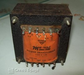
Looking for a power transformer, I saw an Amroh P130.
Amroh was a Dutch radio and electronics trading firm well
known and fondly remembered by many elder Dutch radio
hobbyists for their kits, magazines and books.
They also had their own line of transformers.
The P130 is actually heavier than I needed,
it is specified to deliver 300V at 160mA.
I thought it would amply suit my needs.
When I contacted the seller, he turned out to be an
old friend,
Robbie.
When I told him the purpose I had for this transformer,
he offered it to me for free. Such are friends.
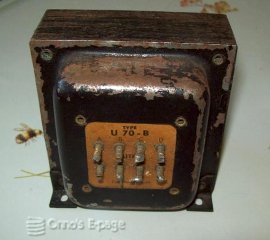
He also had a U70B push-pull output
transformer on sale, which I bought from him.
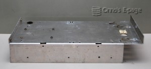
Looking for materials in the junkbox, I found a used chassis
that could be used to carry the output amplifier.
It already had some holes in it, it was a bit higher
and a bit deeper than I needed, but I knew I would
be able to make it fit.
Development
Building an amplifier combo means:
- Building the actual amplifier on a rugged chassis.
- Building the cabinet for the combo and mounting the speaker (driver).
The cabinet design and chassis design are mutually dependent,
as the controls and connectors must be easily accessible
when the chassis is inserted into the cabinet.
I decided to roughly follow the overall set-up of the AC15.
That one has two subchassis, bolted together in an
L-shape.
One subchassis holds the rectifier and power valves
while the other one has all the pre-amplifier valves.
The chassis is mounted in the top of the cabinet, with the
controls and pre-amplifier frame at the back of the cabinet.
This way, it is easy to slide it out but it is more
difficult to create an air flow to cool the output and
rectifier valves.
VOX has made two vents in the top of the cabinet.
On first sight, I don't like that because that will
create an acoustic short-circuit that may
hamper bass performance.
And I don't have the nice grills they had to cover the vents.
It probably isn't all that bad because although the path
from the vents to the front is shorter than
from back to front, the distance from these vents
to the back of the speaker is larger because the speaker is placed
towards the bottom of the cabinet.
Well, VOX must have known what they were doing.
Who am I to criticise them?
Nevertheless, I decided to reverse the chassis and place the
pre-amplifier frame at the front of the cabinet.
This way, it is easy to create
an air flow through the back.
I will mount it on a board that can be slid out
of the cabinet.
The amplifier chassis cannot be slid in straight but must
be lifted somewhat to let the controls pass through
the control panel window.
I have also considered placing the chassis upside-down to
simplify the design.
But I am afraid that this will lead to too much heating up the
components under the chassis.
It isn't uncommon, though.
A lot of guitar valve amps have their chassis
hanging upside down.
I made another change to the original layout:
I didn't like the phase splitter valve living apart
from the output valves on the pre-amplifier chassis.
One practical reason was that I wanted to test the
output amplifier separately before I started building
the pre-amplifier.
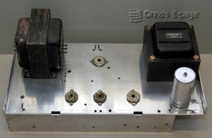
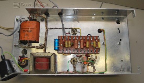
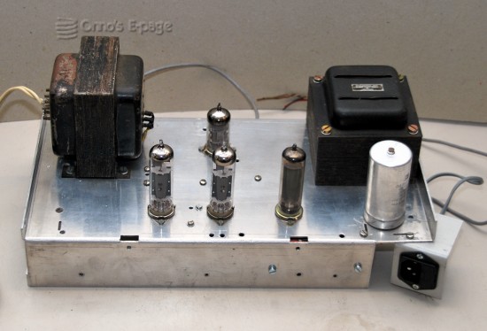
Building the power amp
I started by cutting the holes in the chassis (using a jigsaw...)
for the transformers and valve sockets and drilling the smaller holes.
Then I mounted the large components.
Then I designed the tagboard that holds most of the components.
The wiring to the power connections and the
output transformer
I tied together in a cable harness using wax cord.
This way, the wiring becomes much neater and more robust.
After mounting the tagboard and the cable harness, I soldered
the remaining components and the connections to the valve sockets.
I didn't have an 130 Ω 5 W resistor for the
cathode resistor of the output valves.
I decided to use an 150 Ω 5W Vitrohm resistor
instead (yet another Amroh product).
I thought this would be ok since I expected the
power supply voltage to be somewhat higher than
the original 310V because my power transformer
has a 2x300V winding.
I checked all connections visually and with an ohmmeter.
Then I added a temporary mains receptacle and fuse, connected
a load resistor and soldered a shielded wire to the input.
I inserted two new, no-name brand EL84's, a new ECC83
and a used EZ81 rectifier.
First tests
Now was the moment. Would it work?
Monitoring the supply voltage on the second electrolytic,
I switched on.
As the EZ81 rectifier valve warmed up, the
voltage surged to 440V and dropped again when
the output valves came up.
At this stage, the power transformer was still delivering
2x325V, which is a bit too much.
After the output valves had warmed up, the supply voltage stayed at
360V, which is 50V more than the AC15 had and 60V more than
the EL84's data sheet specifies.
The output valves took 86 mA, as I saw by measuring the voltage
drop over the cathode resistor and over the power supply choke.
The bias voltages of the phase splitter stage were looking excellent.
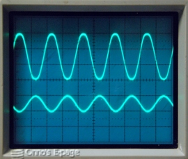
I connected my sine wave generator and saw the output.
It was about 13 W before clipping occurred.
Looked well, but not great.
And why did the output look asymmetric when distortion occurred?
Were the output valves that different?
I hadn't matched them, but they were both new and
from the same manufacturer.
After a while, the asymmetry mostly disappeared.
Trying to measure the bias of the phase spitter again, I saw
something strange happened: the gain suddenly increased.
I realised I had been dumb.
The AC15 has inputs on both grids of the phase splitter.
While testing, I wasn't using one of the inputs and
I had left that input floating.
The result was that the phase splitter could not
function as a differential amplifier like it should.
I shorted the unused input. Much better signal.
After a while I connected a speaker and a music source.
Even on a mediocre speaker, the sound was quite impressive.
When I repeated the measurements with the sine wave,
I concluded the amplifier could produce
15 W at an input signal of 300mV.
Above this, the output is clipped at 30Vtt.
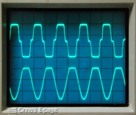
Heavily overdriven using a 2V input signal, the output
valves are drawing grid current, which clamps the
input signal from the phase splitter and shifts their bias.
The cathode voltage raises from 13V to 21.5V here.
The output signal almost becomes a square wave
and has a nasty cross-over distortion.
Time to start building the pre-amp, I thought. But...
Reconsidering…
Doing some quick calculations I concluded I was
overloading the poor EL84 valves.
Not a good idea if the amplifier has to be
reliable.
At first, I thought I could lower their bias current
and put the amplifier further into class B.
But at severe overload, the valves would still
dissipate too much power.
And what would this do to the sound of the amplifier?
Would the extra distortion sound groovy or gruesome?
I decided the P130 was delivering too high a
plate voltage for a pair of EL84's.
(By the way, when I repaired my friend's
Bedrock 600
combo, I discovered some people do run EL84's at even higher
voltages.)
With the U70BN it should be possible to change the
parameters and build a 4*EL84 40W amp.
(Not yet, dear neighbours.).
Maybe some day later I will use it to build a 30-40 W amp.
But for this amp I need a slightly smaller power transformer.
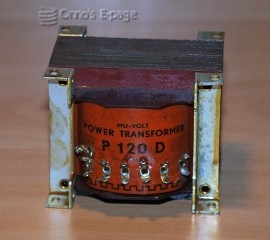
In december 2013 I had also bought an Amroh P120-D transformer.
According to specs, it delivers 2x270V but
only at 60 mA.
But I think the spec is conservative,
as the core is large enough for 80-90 W.
I decided I would experiment a bit with this one.
I replaced the power transformer and switched on.
Now the supply
voltages were more like a common EL84 amplifier.
The power voltage was 300V at rest and 285V at full power.
The amplifier now delivered 9.5 W sine.
The bias current was lower than before so
I changed the cathode resistor to the original 130 Ω.
This got me slightly more power.
Because the output valves are now drawing more current, the
supply voltage dropped to 290V at rest and 275V at full power.
Maybe I need a slightly heavier power transformer.
Or a choke with lower resistance.
Or replace the rectifier valve by silicon rectifiers.
Or be satisfied with 9 W.
After all, that is plenty of sound.
Another point to reconsider was the chassis.
It was a bit deeper and higher than what I needed.
To fit it in, I would have to make the cabinet somewhat
larger than the original.
In the mean time, I had been looking for materials for
the pre-amplifier chassis.
I had been making sketches and found out it was more
difficult than I had thought to make
a professional looking amp using this old chassis.
On top of that, now I had decided to replace the power transformer,
the large hole where the P130 had been would still
be there and spoil its looks.
That part of the chassis wasn't too strong anyway,
because the orginal chassis had an overhanging part here.
Actually, I thought it would look like old junk.
I decided to order some extra aluminium sheet and
make a new chassis.
To be continued.
Copyright © 2014 by Onno's E-page
published 2014-01-18, last updated 2014-08-30