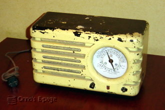
Philips BX373A (1947)
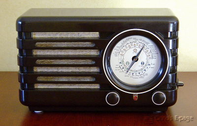
The Philips BX373A is known as “Compass”.
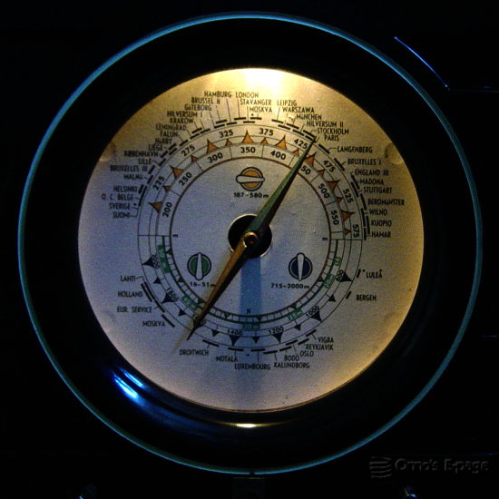
This nickname refers to the round tuning dial with a pointer that
resembles a compass needle.
The pointer is mounted on the shaft of tuning capacitor.
Housed in a neatly designed Philite (Bakelite) case,
it is one of the most wanted Philips models among collectors.
The design of this model is very similar to the pre-war 470A “Sunny”.
The BX373A is nicknamed “Sunny with jittery pointer” or “Compass”.
The nickname originates from the round dial with the pointer
that resembles a compass needle.
The pointer jitters and trembles like a compass needle because it is
fixed on the shaft of tuning capacitor, which is mounted on a set
of springs to absorb vibrations.
As a side effect, the pointer can move a bit with respect to the dial.
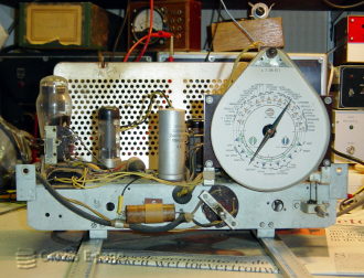
The BX373A is a standard uncomplicated superheterodyne receiver with 3 valves
plus rectifier.
Its valve line-up is:
- ECH21 frequency changer and its local oscillator.
- ECH21 IF amplifier and AF pre-amplifier.
- EBL21 as detector and output amplifier.
- AZ1 rectifier
I bought this radio on one of the
NVHR swapmeets.
It came relatively cheap because it was painted yellow all over.
These radios are usually sold for around €100,-.
The paint was some kind of wall paint or acrylic paint.
The seller claimed the paint should be easy to remove because it was
water based.
He demonstrated that the paint came off easily in small flakes.
On the good side was the very good shape the Bakelite case was in,
it just needed a lot of polishing.
So at home, I first tried to clean the knobs.
I put them in a bowl of water and left them overnight.
The next day, most of the paint fell off just like that.
I disassembled the radio and took the frame, the baffle
and all other things out and put
the case in the bath tub to soak for a night.
Then after a firm scrub, I was able to remove almost all of the paint.
Only on the bottom the paint did not want to come off.
The "artist" who had painted the radio had tried some colors
on the bottom and had sanded the bakelite to make the paint catch on.
Fortunately, he hadn't sanded any of the rest of the case, so it shed
off its coat of paint without any extra damage.
I thoroughly polished it and it shone like a treasure.
Around the dial, there is a circle painted creamy white.
This had vanished as a result of the scrubbing I had done.
I used some acrylic paint, mixed with ocre, to make a fresh new circle.
The radio was a bit dirty when I bought it.
The components turned out to be in good shape.
I measured the leakage currents and it turned out that even the paper
capacitors weren't too leaky. So I decided not to replace them,
even coupling capacitor that usually wrecks the output valve.
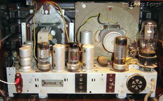
Inspecting the power supply electrolytic, I suspected it was dried out.
The safety valve on top (looks like a solder blob) had some white
crystals around it.
This means that the safety valve is leaking, causing the electrolytic to dry out.
But when I reformed the electrolytic, they had a low leakage current, and
its capacitance was ok.
So I decided to leave it in order to conserve as much of the original
parts as possible.
When I tried the radio, it gave some sound, but weakly.
I replaced the IF valve and it became much better.
Only now the radio squeaked.
I tested the 100μF bypass capacitor in the negative voltage,
and that one was all dried out. No capacitance.
This electrolytic had an oiled paper cylinder as case, sealed at both ends
with a compound looking like brown resin.
I emptied it and hid a modern capacitor inside.
After this, the radio played well, with an occasional crack.
"I will have to monitor that closely", I said to myself.
Only after a few occasions the BX373A started to crack a bit more,
every now and then the volume dropped and the sound generally became awful.
I suspected the coupling capacitor had started to leak and I decided
not to use it any more before I had fixed it again.
In November 2006 I started the second repair.
I found out that all the voltages were OK.
The plate supply was 285 V, the grid bias voltage -5 V.
The voltage on the grid itself was slightly more positive, but no so much as
to fear that a leaking coupling capacitor was slowly demolishing the output valve.
Strange things happened when I poked around with my measuring prods.
When I touched the filtered power supply, the radio suddenly started to
play harder.
When I touched the frequency changer or the IF valve, the sound became worse.
I cleaned the valve sockets which removed the cracks caused by the IF valve,
but not the ones for the frequency changer.
After I swapped that valve, it stopped causing cracking noises.
The sound was better now, but it still faded and became distorted a few
minutes after switching on.
When I touched some points in the power supply, the sound became stronger
to fade away again after a few minutes.
Using a scope, I could not find any spurious oscillations linked to this
behaviour.
There was some IF signal on the output tube, but it was constant, seemed
to be caused by some crosstalk from the detector sections of the EBL21.
I started to suspect the output valve itself.
The grid voltage went up slightly as the valve warmed up.
I tried a few spare EBL21's and found one that functioned perfectly.
So it was the output valve after all, and I seemed to have at least
5 bad EBL21's in my valve box.
Now my BX373A is working great and gives a steady and undistorted
sound, much better than after the first repair.
I hope it will stay that way.
I will still have to monitor it closely.