Philips BX480A radio (1949)
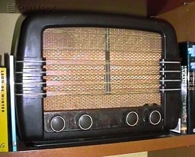
The BX480A is a lower mid-range radio in a bakelite case.
The a mix of valve
generations used reflects the era it was built.
This was one of the first radios in my collection,
given to me by a friend.
It unites 3 generations of valves: Loctal base (20-series), a Rimlock base (40-series) and the old P-type (side-contact) base (00-series). An ECH21 is the frequency changer and its oscillator, the IF and the first AF stage are both EAF41. The output stage is an EBL21 that is also the detector and the rectifier is a good old AZ1. There is no tuning indicator.
Someone had slightly modified this radio by adding 4 receptacles at the back, apparently to supply power to another device, maybe a gramophone pre-amplifier. This person had added an extra choke in series with the outgoing HV supply that was fixed to the loudspeaker baffle.
I was given this radio by a friend, who inherited it from her father. When I tried it, after cleaning out the dust, it worked fine (I used a Variac to power it up slowly and let the electrolytic capacitors recover from their sleep). I placed it in my living room and every now and then I listened to an AM-band "golden oldies" radio station. By listening somewhat longer, I found out that the tuning slightly drifts in the first 20 minutes or so. This is probably thermal drift from the oscillator, so no big deal.
However, after a while the radio started to squeak every now and then, after a warm-up of 45 minutes. After a month more it added loud cracking noises that were independent of the position of the volume control. Besides, the sound was becoming a bit thin.
So I opened it up again and started the repair seriously. It turned out I should have done that earlier. The HV was too low, only 90 V. I checked the voltage before the rectifier valve but that was ok. I was lucky to have a spare AZ1 at hand. Swapping the rectifier resulted in a higher HV of 230 V.
I suspected the cracking might come from the AF coupling capacitor breaking down. I checked the negative grid voltage on the output tube, which was too low (only -4 V). Swapping the capacitor resulted in a higher voltage (-5.5 V), while the HV became slightly higher too (due to the lower quiescent current in the output tube). But the cracking remained.
I inspected the AF pre-amplifier tube. The pins were silver-plated and very blackened. Cleaning them by mild abrasion and some contact spray made the cracking disappear. Now the sound was much better than before, and the radio was able to receive much more stations (due to the higher voltage on the RF and IF section). I happily put in back in my living room.
However, after a few days it started "motorboating", i.e. a low-frequency oscillation, probably in the AF section. This disappeared again. After this, the radio has been playing fine for a number of years.
As you can see on the picture, there are some stains on the copper plate behind the control knobs. They have the shape of water drops, with grains of green/white copper salts on the edges. I decided to try to remove these by polishing them away. I wish I hadn't.
The polish also remove the brown color of the copper, and even worse, it revealed that the copper plate was a brass plate that is copper plated. I polished through some of the red copper. Afterwards, the copper plate was much too shiny. This improved gradually, but the color differences between brass and pure coppe have remained. At the same occasion, I also polished the Philite case. That turned out just fine: the case looks like new aagain. (I should make photographs of this to document it)
Copyright © 2000 - 2008 by Onno's E-page published 2000-10-06, last updated 2008-10-12