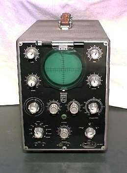
Philips GM5653 oscilloscope
This scope has been built around 1950.
It is a nice scope, having a stabilised power supply.
According to Philips, the 3 MHz bandwidth is sufficient to display
TV signals.
I bought it to get a scope cheaply, but it was not the bargain I hoped for.
The GM5653 scope has a
specified vertical 3 dB bandwidth of 3 MHz, which the manual
says is sufficient for the display of TV signals.
It has a free-running timebase
that is synchronised with, not triggered by the input signal.
The CRT has a 10 cm round screen with a usable surface of 6x8 cm.
An acrylic window hinged at the top has the reading scale on it.
This scope originally weighed 26 kg.
It contains 18 valves, which includes the DG10-6 CRT. Most of the valves
have an 8-pin Rimlock base (pro-electron 40-series).
I didn't realise how old it was when I bought it on a
flea market in Leiden in 1985.
Actually I was looking for a cheap scope for hobby use.
When I tried it at home, it turned out not to work properly.
Brightness was too high, the spot was not blanked on fly-back and it
was nearly impossible to synchronise the timebase.
Above all this, the image was distorted and showed mains interference.
When I opened the enclosure, I was in for an unpleasant surprise.
A previous owner had badly mistreated this piece of equipment.
Part of the power supply seemed to have disappeared, as there was
quite a large empty space near the power transformer. In this
space some silicon rectifiers and power resistors were
dangling by their leads like dead insects in a cobweb.
For some reason, the mu-metal magnetic shield round the CRT
had been removed, too.
Fortunately, I could borrow and copy the owner's manual
at the electronic equipment maintenance service at
the Delft University.
It turned out that in the empty space there should have been 2
subframes, one rectifier frame carrying 4 rectifier valves,
the other containing a regulated power supply frame
with 4 valves: EF42, UL41 and twice 85A1 (a neon voltage
reference valve on a Loctal base).
The regulator circuit had been replaced by a series resistance,
which will obviously not result in better regulation.
I also discovered why I had mis-judged the scope's age:
on the photographs in the manual it had black, very 1940-ish
style knobs.
These had been replaced by grey knobs of a type that
Philips used on equipment produced in the 1960-ies.
Though the photocopier wasn't particularly good at photographs,
you can recognise the style of the knobs here on the right.
I decided to try and get the scope back in working order.
As I did not have any AZ41's, I decided to use silicon
rectifiers.
The BYX10 rectifiers hanging around were not suitable though for
the voltages in the scope HV supply, so I replaced all of them by
BY127M. I added series resistors and snubbing capacitors to protect
the rectifiers and mounted all on a piece of phenolic perfboard.
The regulated power supply was quite a bit of work.
It is essential because the the timebase and pre-amplifiers need a
stable supply with negligible hum to work properly.
The neon stabilizer valves had been replaced by two strings of zeners
to get stable + and - deflector bias voltages.
Originally, the + stable voltage
was also used as the reference voltage for the power supply.
Though the zeners did their job, they were hardly an
elegant replacement in a valve-based power supply.
I decided to replace the zeners by neon stabiliser valves again.
I had some 85A2's, these have a 7-pin miniature base.
Yes, I know, that is an anachronism too, but I did not have any 85A1's.
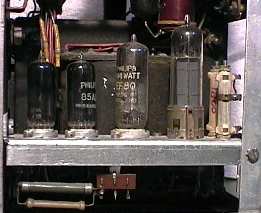
I made a new regulator subframe from sheet aluminium and
mounted a UL41 and an EF80 (did not have an EF42), and the two
85A2's on it.
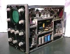
The result is on the photograph at the left.
The replacement regulated power supply worked fine. I set it for
210 V. The timebase worked much better now. But
brightness control was still bad and trace blanking didn't work.
The cause of the brightness and blanking problems lay in the
capacitors that had been used to replace the coupling capacitors
between the timebase and the CRT. These convey the blanking
signals.
They work at a high DC voltage (1400V divided over 2
capacitors) and had probably started leaking, as old paper
capacitors usually do.
They had been replaced by 400V types, which is asking for trouble.
I replaced them by 1000 V types and after that, blanking and
brightness control were OK.
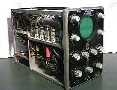
On the two photographs below you can see several brightly coloured
capacitors that are obviously not original.
Finally, I discovered that a reservoir capacitor in the HV supply had
been removed.
I replaced it and also replaced the parallel voltage
division resistors, one of which was interrupted, probably having
caused the failure of this capacitor.
You can recognise the blue electrolytics on the photograph at the
right. They're on the lower deck.
I did not use the scope much after all this work.
After all, it does not have very good specifications.
The timebase is impractical and bandwidth is limited.
The worst thing, however, is that the mu-metal magnetic shield of
the CRT has been removed by the previous owner.
This affects the image stability and sharpness.
Well, it is a piece of "antique" after all.
But for a historical piece of equipment too many things have been
changed.
I'd like to replace the knobs, if I had some original ones.
Chances of finding a replacement mu-metal shield are practically zero.
I might redo the restoration of the power supply and put in the right
valves (EF42 and 85A1).
After the restoration in 1985, I did stumble across some
85A1 reference valves on a flea-market.
Unfortunately, only 2 of the stabilisers seem to be within specs,
so I won't have any spares left.
The voltage and internal resistance of the other ones have become too high
*
On the rectifier side, I still don't have enough
AZ41's.
I could do all this when I had too much time,
but the added value would be marginal
*
By the way, does anybody know what the failure
mechanism behind this is? Is the neon mixed with some
other gas, from outside or from evaporated material inside?
OTOH, the getter is still shiny. Or maybe the neon gas has partly
vanished, e.g. absorbed in metal parts?