Philips PE4801/00 regulated power supply (1960)
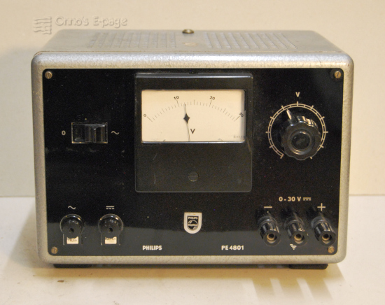
The PE4801 is an early low voltage regulated power supply from Philips.
It has four germanium transistors doing the regulating and a
neon glow discharge tube as a voltage reference.
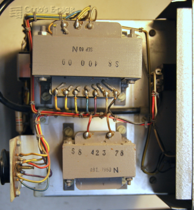
View of the inside on the left, power transformer and choke.
On the NVHR site I found documentation, including the circuit diagram. The circuit is quite simple: a series transistor in a darlington configuration is driven by a one-transistor error amplifier, that tries to copy the input voltage from the voltage control. This input voltage is derived from a floating 85V reference voltage. The line-up of semiconductors and valves is:
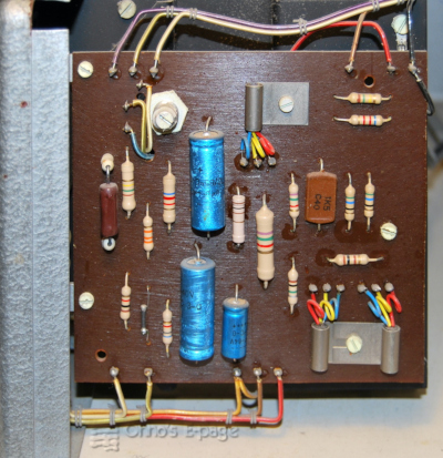
A view at the PCB with the control circuits.
Early 2026 I decided to try this power supply again and get to know it better. I checked the condition of the electrolytic capacitors. These were ok. Then I switched it on, regulating the mains voltage. The 85A2 lit. But the output voltage was low and the voltage control did nothing. I measured the voltages in the circuit and was a bit puzzled. The error amplifier transistor didn't seem to work. I didn't have a spare OC77 (where do you find a Germanium transistor with a Vceo of 60V?) but an ASY77 should do. It didn't make much difference.
Checking again, I found that a resistor in the feedback circuit seemed interrupted. One of the solder joints was interrupted, it was badly soldered. I looked and found several other suspicious looking solder joints. After correcting these “dry joints”, the PE4801 was working.
There was one more strange thing. While measuring, I noticed that the chassis was somehow connected to the unregulated −45V power supply. That didn't make sense. The collector of the series transistor and heatsink are also connected to the − power. The heatsink has isolating mounts with a reason. I saw that one long M3-screw that holds the PCB to the heatsink was a few mm too long and was touching the chassis, causing a short. A 66-year old production fault. This hadn't caused damage to the power supply itself but it must have caused problems in use. I cut 3 mm from the screw and the circuit was floating again relative to the chassis.
Then I soldered the original OC77 back in place and had a PE4801 that was working well. The meter showed that it responded well to the voltage control and the output voltage remained constant when loaded.
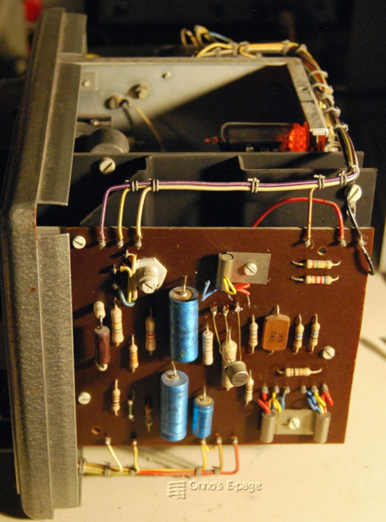
After first repairs, working fine with a temporary ASY77, neon stabiliser lit.
Copyright © 2026 by Onno's E-page published 2026-03-14