QUAD 405 amplifier clone
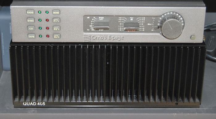
I had two spare clones of the QUAD 405 amplifier modules and wanted to do something with them. The obvious thing was to build an amplifier. That is what I did.
In 2018 I acquired a QUAD 405 amplifier. The previous owner warned me it was defective, but her information on this was equivocal. On the one hand she sad it had some kind of hum, which sounds easy to fix. On the other hand she said the amplifier caused a short-circuit once, which in my understanding could have been caused by anything from a fault in the power strip she had used to a short in the power transformer or a completely fried amplifier module. To prepare for the latter I looked around and saw that Quad 405 amplifier module clones are easy to find. So I ordered a kit for two Quad405 amplifier modules on eBay. I chose one that had MJ15024 transistors, these have a TO-3 case like the transistors in the original 405. As it turned out my original QUAD 405 was easy to fix. So I had two spare amplifier module kits, looking for a purpose. I decided to build a QUAD 405 clone amplifier. Again on eBay I ordered a black imitation QUAD 405 cabinet.
In February 2019, I started to build.
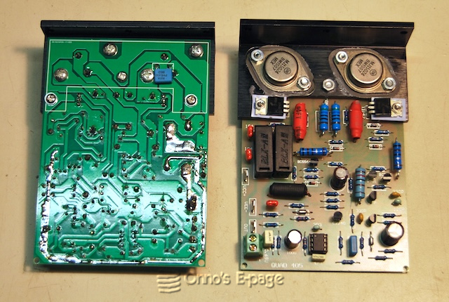
First I populated the PCB’s. No schematics came with the kits but scans of the original QUAD 405 service manual are abundant on the Web. There are several versions of the schematic. On the PCB’s, component types and values were printed. Comparing with the QUAD manual, my PCB’s corresponded best with version “PCB12368 issue 9&10”.
Then it was time to mount the power transistors and fix the board to the heatsink T-bar. The transistor mounting holes in the T-bar were drilled larger to allow for M4 screws and some insulation tubing.
The resulting modules were looking great.
Then the cabinet arrived. It was higher than the original Quad 405 cabinet. Never mind.
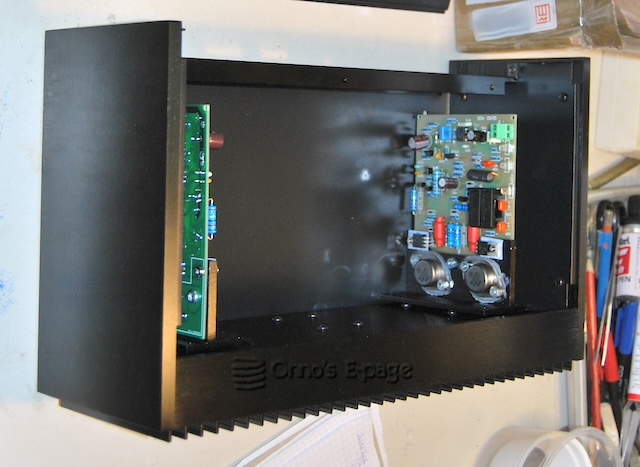
I mounted one amplifier module on the heat sink. The holes in the T-bars of the amplifier modules aligned exactly with the holes in the heat sink. Splendid. A smackerel of thermal compound was used the heat sink and the T-bars. The rectifier bridge also found a place on the back panel.
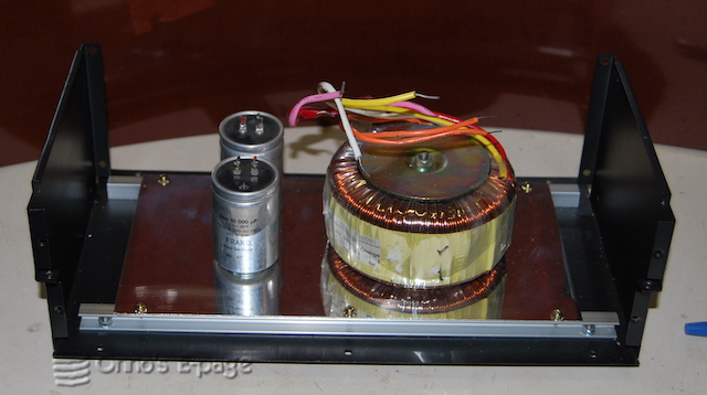
I built a sub-chassis to hold the toroid power transformer, buffer capacitors and other extras. So the only hole in the bottom of the cabinet was for the bolt that holds the transformer, to solidly mount the power transformer.
Then I carefully tested the amplifier using two lab power supplies, initially set for a low voltage. Everything was looking ok. When increasing the voltage the amplifier remained stable. I connected an input signal and saw it amplified and delivered into the test load.
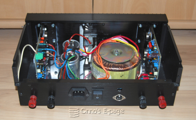
I had gained enough confidence to connect the power cord and try the first amplifier module using the amplifier’s own power supply. It had measured 48.5 V on both electrolytics. Nothing disturbing happened. It just amplified. I turned the signal up to get over 80 Vtt on my test load without visible distortion. The module was delivering 100W. Beyond that, it started to clip, but worse, it showed some oscillations around the clipping point. Test load was hot. Heat sink lukewarm.
I mounted the second amplifier module. I also fitted a QUAD-style 4-pin DIN input receptacle at the back of the cabinet and wired the second module to it. I tested the amplifier with different signal levels and noticed that some resistors were getting rather hot. After a minute of 100W I smelled a whiff of overheated epoxy. It seemed one of the transistors was getting hot. I removed the input signal and touched the transistors. Both the TIP42 and the MJ15024 were really hot. I touched the small signal transistors but couldn’t find if any was overheating.
At one point I removed the input lead from the generator and touched the input. Immediately the amplifier started oscillating wildly, rail to rail. A puff of smoke rose somewhere from the module. I removed my finger. It was unclear from what component the smoke came from. After this, I tested the amplifier at 50W for 15 minutes. It just carried on, though the TIP42 was getting quite hot. The temperature of the heat sink was 54°C. Couldn’t measure the temperature of the small signal transistors, because the spot size of my IR thermometer was too large. The TIP42 gave a reading of 75°C but that may be off.
After this, I tested the amplifier at 100W for 5 minutes, after which the sine became distorted. The DC voltage on the output had risen to 11V (from 40mV). This was not okay. Switched it off quickly.
On 3 June I decided to repeat the load tests on the first channel. Again the smell of epoxy at 100W. I reduced the signal to get 50W. I checked all the voltage levels indicated in the circuit diagram, which were well within range. After 15 minutes at 50W things were stable but the transistors were hot.
So I had an amp that worked but tended to HF oscillate when its input was connected to a large ungrounded conductor and to have some transistors overheat when operated at full power. Not very trustworthy yet. I was getting a bit annoyed and impatient and decided to try it with music anyhow.
On 8 June I connected it to my speakers and QUAD 34 preamp. It sounded really good. Loud music was no problem. The actual power output was still modest, this was only my living room. After an hour, the heatsink was only just lukewarm.
So it sounds great and it didn’t fry my speakers. But I don’t trust this amplifier enough to set it up for daily use. I must add a speaker protection. For which I don’t really like the original QUAD “kamikaze speaker protection” as Douglas Self calls it, that has a thyristor to short the output when danger occurs. It also needs a soft-start unit as sometimes the inrush current of the toroid power transformer blows the main fuse, which is annoying.
So I will have to make some additions to this amplifier.
