μTracer valve characteristic tester (in progress)
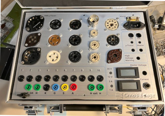
When you are using thermionic valves, it is always handy to have a valve tester at hand. It is even more useful to have a valve characteristic tester, to not only check emission or measure transconductance, but also plot the characteristics of your valves. But good valve testers or advanced instruments such as the AVO Valve Characteristic Meter are hard to come by. After a friend of mine told his enthousiastic story of the μTracer he had built, I wanted one too. I contacted the designer and ordered a kit. The project is almost finished now.
I have often considered building a valve tester but never got to it. It is complex, components such as special transformers are hard to find. It is a lot of work. In 2025 I met an old friend and fellow hobbyist who told me he had built the μTracer valve characteristic tester from a kit. I had heard of this interesting design before but I never thought I would be building one myself. After this conversation I was convinced I needed to have a μTracer and build one.
The μTracer is a microcontroller-driven test circuit providing four controllable power supplies and voltage and current measurement circuits to test thermionic valves.
- Plate voltage
- Screen voltage
- Negative control grid voltage
- Heater voltage
The actual tests are performed using pulsed voltages. This limits the continous power the tester needs and the amount of stress on the valves under test, allowing to perform tests above the maximum continuous power dissipation rating of the valves and achieve realistic dynamic working conditions.
Tests are controlled from a GUI running on a Linux, MacOS or Windos system. The GUI sends commands to the μTracer to set test voltages, perform tests and return the measured values.
I contacted the designer of the device on the μ-Tracer site and ordered a kit.
Building the μTracer
The kit arrived in good order and I started building. The manual that comes with it is very detailed and it meticulously describes the steps to build the μTracer and test every subsystem after building it.
I installed the GUI on Ubuntu Linux under WINE. I had ordered a USB-to-serial converter with the recommended FTDI chipset. There were a number of hurdles to be taken to get WINE to use the serial converter and hand it over to the GUI, but the software was working after a number of tries.
Lying on my workbench, the μTracer board was working fine and I was able to perform all tests and callibration procedures.
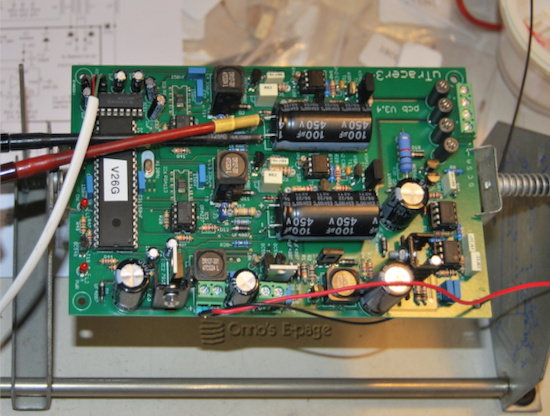
Building the μTracer board and making it work only was the first stage. Now it was time to make a test panel with the necessary valve sockets, mount everything in a suitable case and add all the extras needed.
I designed the front panel using LibreOffice Draw. Making the front panel itself took a lot of drilling, cutting and filing. I printed the lettering on a transparent sticker and stuck it on the panel after drilling. I used a spray varnish to protect the ink. But before continuing, I needed to decide on the heater supply.
Heater power supply
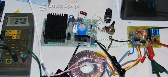
When you read about the μTracer, one thing that is mentioned often is that the heater supply is not optimal. Many people who have built the μTracer, use a separate heater supply. So I decided to include an external power supply. My friend had used a ready-made switch mode power supply module including digital meters. But as I have lots of stuff lying around, I wanted to reuse something from my treasure cache. I found a linear power supply module, H-Tronic model HB-533. As I write this, it is still available as a kit or ready-made module on Conrad electronics and many other sources.
The module is rated 1-30V at 0-3A, but beware, the heatsink is only suitable for a dissipation of 20W. It has two BD249C series transistors and the control circuit is based on an LM723. I was able to download the circuit diagram from the Web. Compared to other 723-applications, it has some special features:
- The output voltage can go as low as 0.8V;
- The current limiting resistor is placed in the ground lead instead of in the plus lead, so the current limiting transistor in the 723 will have the full output voltage over it.
- Also, a small additional voltage (100-700mV) derived from the reference source of the 723 is added to the voltage from the current limiting resistor. This allows for a variable current limiting action, which is quite remarkable for a 723-based power supply.
Daring, but it seems they have sold quite a few of these units so I guess this circuit should work.
For mains transformer I selected a toroid transformer having two 12V windings. I used a relay to switch the secondaries in parallel or in series to supply 12V~ or 24V~ depending on the desired output voltage. This helps to limit the dissipation of the series transistors. Using a single rectifier connected to the top of the lower secondary, a buffer capacitor is charged to 16V DC for auxiliary supply, with its return path through the negative side of the bridge rectifier in the power supply module. When the two secondaries are in series, the extra diode is at the center tap of a 24V secondary, resulting in the two negative-side diodes of the bridge rectifier acting as full-wave rectifier to charge the buffer capacitor, again resulting in 16V DC. This 16V supply is used to actuate the relay.
The DPMs need a 9V power supply. Their inputs must be somewhere in between the supply rails. Therefore, I built a simple auxiliary power supply giving +4.7V and -4.3V respective to the -lead of the power supply module. The 4.7V supply is derived from the 16V auxiliary supply with a zener diode. For the negative auxiliary voltage, I used a charge pump circuit, looking like a voltage doubler, and stabilised it to -4.3V with a zener.
Finally, I added a small extra relay to add an extra current limiting resistor when the power supply is switched to the 30V range. This is to limit the maximum output current to about 1.2A, again to protect the module from overheating. (maybe I should have added temperature monitoring, now I will still have to be careful not to overheat the power supply)
The relays and auxiliary power supplies are built on an additional circuit board. I tested the auxiliary board with the power supply module and it was working as desired.
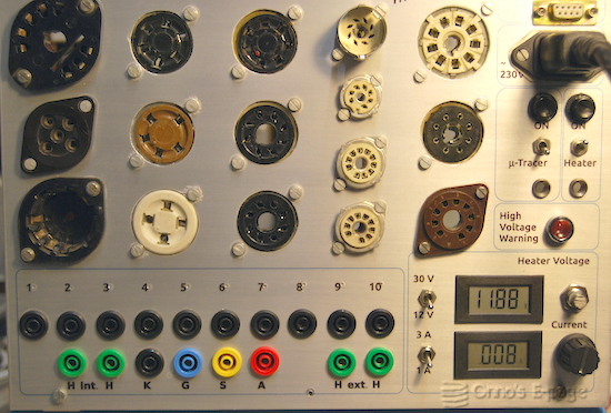
I mounted the two DPMs for the heater power supply on the front panel. To the left of the meters, there are the two range switches marked 12/30V and 1/3A respectively. Actual meter ranges are 20/200V and 2/20A but the power supply will only deliver 30V or 3A maximum. The voltage and max. current controls are placed to the right of the meters. A multi-turn pot is used for the voltage control and a regular potmeter for the current limit control.
Building all together
I used an aluminium toolcase (suitcase) to have a portable unit. I ordered an aluminium sheet chassis, plied in a U-shape fitting in the case, along with a 2 mm front panel.
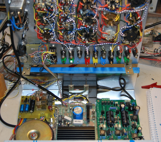
The chassis holds the circuit boards, the toroid and the laptop power supply for the μTracer itself. On the front panel, I mounted 16 valve sockets and 18 banana plug receptacles to make the valve connections, separate on-off switches and fuses for the μTracer and the heater supply, the mains receptacle and the communication port. And some pilot lights.
To be continued.

Copyright © 2026 by Onno's E-page published 2026-08-16 last edited 2026-09-19