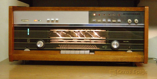
Philips B8X44A radio (1964)
The B8X44A was a Philips top radio.
It was one of the last "Plano" models, as the "Plano" form factor
was becoming less fashionable and flat case audio equipment with
separate speakers came en vogue.
This model has FM stereo, and "Rapidosound" and
"Intercom" functions.
Its sound is good, but the bass is not really great, in spite of the
large speakers.
The B8X44A is a so-called "Plano" type of radio: radios that
came in a low-profile cabinet with the built-in speakers on the sides.
This was an expensive luxury model.
It has a veneered case in Scandinavian style and must have been modern and stylish.
It is an early FM stereo model, stereo broadcasts in Holland
having started in 1963.
As an extra feature, extra speakers in adjacent rooms can be connected that can be
switched on and off and be used with the "Intercom" function.
That is, if you push one of the "Intercom" buttons,
one of the speakers in the radio is used as a microphone, and
the signal is output to one of the external speakers.
This model also has a "Rapidosound" button, a
Philips word for "stand-by".
It means the heaters are kept warm so that when you switch the radio on,
you will have sound immediately.
Handy with the Intercom function, maybe.
The radio contains 9 valves and a number of semiconductors:
- ECC85 for FM rf amplifier and frequency changer,
- ECH81 as AM frequency changer and 1st FM IF,
- EF89 as AM/FM IF amplifier,
- EF183 as 3rd FM IF amplifier,
- ECC83 as pre-amplifier for left and right channels,
- 2x ECL86 as second AF amplifier and output amplifiers,
- EM84 tuning indicator and finally an
- EZ81 rectifier.
- AA119 germanium diodes as AM and FM detectors.
- 1 AF124 and 2 AF126 HF transistors and a number of
AA119 diodes in the stereo decoder.
- An AC172 transistor serves as a pre-amplifier for the intercom function.
- The driver circuit for the stereo lamp, finally, uses 3 small-signal
germanium transistors.
I got this radio in a barter for the
B7X14A luxury plano.
I wanted a plano with FM stereo that covered the full FM band.
This one looked like it did not need much work, just some cleaning. Well...
Something within the FM tuning mechanism was a bit stuck, so the
needle only moved from 90-95 MHz.
One of the metal skins of the pushbuttons was missing.
And none of the pilot lights worked.
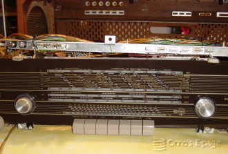
So I started the repair, which is a risky task with this one.
Before you can even think of taking the chassis out of the case,
you'll first have to disconnect and remove the speakers.
Then you unscrew a couple of nuts to release the brackets that hold the
pushbuttons, pilot lights and balance control wheel.
After that, you can remove the bottom screws and carefully slide the chassis
out.
On your workbench, it will rest on the tone control knobs and the
pushbuttons for the frequency ranges.
The brackets with pushbuttons for the extra functions and the
pilot lights will dangle by their cable harnasses,
that are not long enough to put the brackets safely beside the radio
so you must constantly check you are not causing a short circuit.
There is no easy way to stand the chassis on its side.
You'll have to use plastic boxes and miscellaneous support material to
keep it from falling over.
I broke one of the pushbutton switches when trying to stand the thing
upside down.
Fortunately, the broken pertinax (phenolic paper board) part could be
repaired using 2-component epoxy glue.
I dusted and cleaned the inside and noticed the driver board for
the stereo pilot light was dangling loose.
The fixing screw had disappeared.
After replacing the pilot lights, I noticed that the stereo light
never lighted.
Measuring the signals on the stereo board, I saw that the pilot tone
feeding into the driver board was very weak.
But I did seem to hear a little bit of stereo sound,
so it could not be the stereo decoder?
Well, yes.
I opened the stereo decoder and measured the signals.
It looked like the pilot tone was very weak.
Feeding the decoder a 19 kHz test signal, it turned out that the pilot
tone amplifier, a selective amplifier with two LC circuits,
was misaligned, because it peaked at 21 kHz instead of 19.
I studied the circuit diagram to fathom the secrets of the decoder.
After that, I was confident to try and adjust the pilot tone amplifier,
though there are no
adjustment instructions in the service manual.
This worked. After aligning the coils in the decoder, the amplification
of the stereo pilot tone went up by a factor of 50, which was enough
to drive the decoding matrix and markedly improved the sound.
The pilot light did light now, but only on the strongest of stations.
I replaced the small electrolytic that smoothes the rectified pilot tone,
and that did the trick.
I also checked the detector curve of the FM detector.
I must admit that is was not as symmetrical as desired, but after all
the trouble with stuck and broken cores I had had
adjusting the
B7X14A,
I decided the slight improvement to be expected wasn't worth it
These Plano radio's have a diffusion screen to spread the light
for the tuning scale illumination.
This is a sheet of plastic suspended by 4 springs.
As in many other planos, the plastic sheet had become brittle and cracked.
It had fallen down and blocked the movement of the tuning mechanism.
I replaced it by a sheet of drawing film. This is a mylar film
with a matted coating on one side. It is slightly more transparent than the
original film but does the job well.
After this, I cleaned the cabinet and knobs thoroughly and treated the
wood with a liquid furniture wax.
The radio was playing very well after this.
The sound was rather good, better than most of my other radios.
This must be attributed to the large speakers.
But it tends to distort when the volume is turned higher.
And the bass is not really what it should be.
This is probably caused by the very small output transformers.
Except for this, I was very satisfied with this
last-generation valve radio and I have used it for years