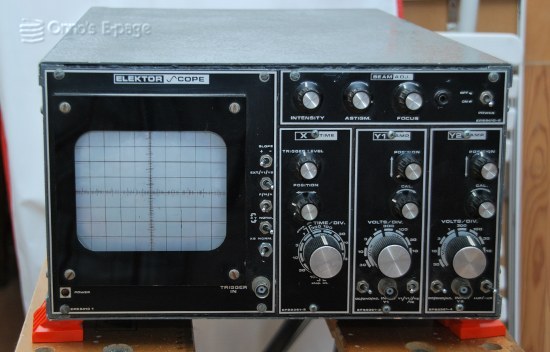
Elektorscope
This is quite a unique scope.
It is a home-built scope after the “Elektorscope” design
by the Dutch electronic magazine Elektuur.
Anybody who loves scope kits should understand how unique this
DIY scope is. It has been built after the Elektorscope design.
From February 1975 until February 1976 Elektuur ran a series of
articles on this DIY scope design.
These appeared in the international Elektor editions a year later.
It had a modular set-up: one had the option to build either
one or two input amplifiers.
One could choose between a 7 cm or 13 cm CRT.
You could use any CRT you happened to have, on condition it was
sensitive enough.
Elektuur sold PCBs and front panels for this design.
The front panels were modular: a front panel for every module so if you'd
want to build a four-channel scope, you'd have four four amplifier front panels.
They had two types of front panels for the CRT: a small one for 7 cm CRTs
and a larger one for 10-15 cm tubes.
I read the series of articles a few years after publication and became excited
about the idea to build a desirable instrument such as a scope myself.
But I didn't have the time nor the money so to build an Elektorscope
remained a dream.
Recently, I saw an Elektorscope on an Internet auction site.
The person selling it hadn't built it himself but the device had been
given to him by the original owner.
He showed me the CRT had a trace with showing some kind of distorted
square wave.
Maybe the signal of the two-channel adapter (what else could the signal be?).
He couldn't measure anything with it.
We reached an agreement and I took home quite a heavy scope.
My Electorscope has a largish (12 cm) crt and looks like the original
builder has done his best to make an impression.
I don't share his taste for grey paint with sand sprayed all over though.
This might have been an attempt to imitate wrinkle finish as used on
old professional measuring equipment.
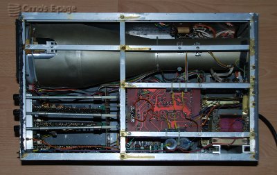
At home, I removed the lid of the case to take a look inside.
The frame is constructed from aluminium U and L profiles and flat sheet
aluminium, cut to size and bolted together.
This is a simple but effective construction, if you don't have the
means to ply aluminium sheet.
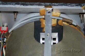
The large CRT is surrounded by a magnetic (mu metal) shield.
I cannot see what type the CRT is.
And because of the, ehm, resourceful construction used to mount the CRT,
it is not really easy to get access to it.
The constructor doesn't seem to have tried to saw the shield to size.
This is fortunate because the specific type of alloy used for these shields
is hard to work and looses its high mu when mistreated.
In the back, there are two power transformers.
One has a number of low voltages, presumably for the pre-amplifiers.
The other is mounted beneath the first one, this seems to be an HV type,
needed for the CRT supply and output amplifiers.
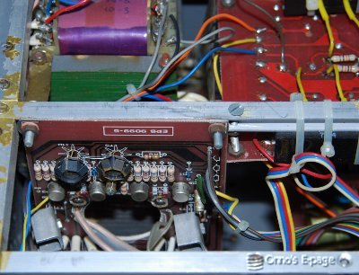
There is a HV power supply PCB with some odd capacitors mounted to the
frame. These are presumably part of a voltage doubler.
I will collect my old Elektuur magazines and see what needs to be done to fix
this unique old scope.