Philips GM2317 signal generator (1954)
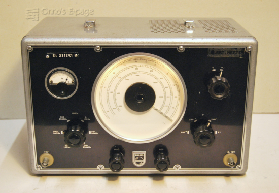
This is an LF generator producing sinewaves from 20 Hz to 250 kHz.
I bought it from a collector in 2002, just because
it was interestingly old.
It turned out a useful instrument
to be used for years until it broke.
In 2026, I restored and repaired it.
The GM2317 is an LF generator introduced by Philips around 1953.
The model has been sold for more than 11 years, going
through a number of changes during that period.
Although my GM2317 is an early specimen, from 1954,
it already has a number of improvements that
are not documented in the 1953 service manual.
The GM2317 uses the Wien-bridge oscillator principle.
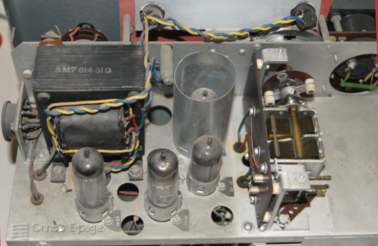
The valve line-up consists of Rimlock types:
| EF40 | pentode as pre-amplifier, |
| EF40 | pentode as second amplifier stage, |
| EL41 | power pentode as output stage, |
| AZ41 | rectifier. |
It also has four OA70 germanium diodes as a bridge rectifier for the output meter.
The three amplifier valves form a 3-stage non-inverting amplifier.
The EL41 is configured as a cathode follower, a low-impedance buffer at the output.
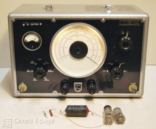
Except for the missing handle. the generator was in good condition when I bought it.
It had an inventory label on the front and a glue residue from a label exposing the text
“ELEKTR.MEETT.” which is an abbreviation of
“Electronic Measurement Technology (Laboratory)”.
After checking the capacitors and slowly starting the generator
to let the power supply electrolytics reform, it just worked.
I found that the coupling capacitor from the first to the
second stage was leaky, but I did not replace it at the time.
I have used it for years until I collected more AF generators to use.
The GM2317 wasn't always stable as it should be.
My notes say that the amplitude tended to vary and sometimes suddenly
the signal was distorted. This may have just been the automatic gain control
from the incandescent lamps swinging round the set point.
Somewhere around 2015 the output meter stopped working and
the tuning knob didn't work any more.
So I put it on a shelf to fix it sometime later.

Inspection
In early 2026, after fixing the
GM2885
RF generator, I decided to take up the GM2317.
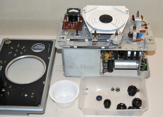
I opened the cabinet and dusted the inside.
At further inspection,
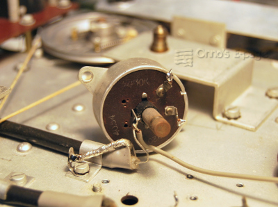
the GM2317 contained four incandescent lamps where I expected two.
The schematic in the 1953 manual shows two incandescent lamps used
as the cathode resistor of the first stage.
They are part of the negative feedback loop and their power dependent resistance
must stabilise amplification to limit distortion.
I traced the circuits and drew a schematic.
It turned out that the four incandescent lamps are on a different place
in the circuit.
They are in series with the
positive feedback circuit, regulating loop amplification.
The same circuit is found in the later GM2317/01 through /04
versions, but those models have other types of
valves and a number of small additional refinements.
So what version did I have?
I checked production codes on the capacitors and other components
and found dates in 1954.
There was a label on the front that read
“Et2317/01” but this was not the type label,
merely an inventory label of the
lab that had once owned this instrument.
The type and serial number label at the back simply
read “GM2317” without revision number.
It couldn't be a GM2317/01, that has Noval valves and is from 1959.
So was this a GM2317 without “/”, but with improved circuitry?
I did some research on
Radiomuseum.org,
Dutch Forum on Old Radios and
the NVHR site
and found that while this improved version of the GM2317 with Rimlock
valves was not documented as far as I could find, but
there were more GM2317 specimens from the mid-fifties with Rimlock valves
that were fitted with four incandescent lamps.
Repair
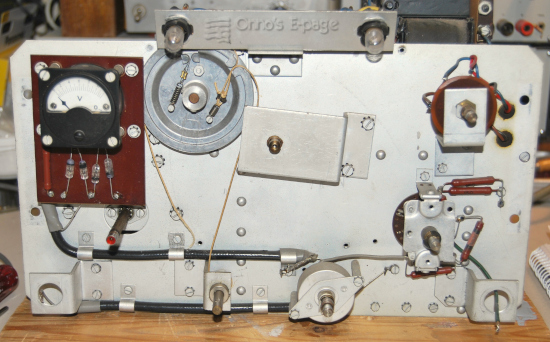
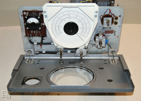
I started the obvious repairs. The driving cord had snapped.
I removed the front to get to the tuning mechanism.
Following the manual, I made a cord of 440mm. Giving it 3 turns round the
shaft of the tuning knob, it fitted.
One of the resistors in the output divider was burned and
its resistance had increased.
I replaced it by 2 precision resistors in parallel,
to get the right value of 680Ω.
When I measured its value and the other resistors, I noticed that the
output meter moved only with the ohmmeter leads in one direction, not when
I swapped the leads.
It has a bridge rectifier so it should react to both polarities of the ohmmeter.
One of the four OA70 germanium diodes was indeed interrupted.
I replaced the defective diode and tested the meter again. It was OK now.
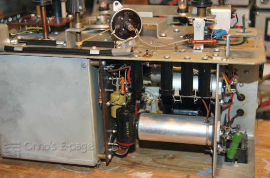
Then I unsoldered the leads to the power supply electrolytic capacitors
to reform and test them.
There is a voltage
divider (R49+R50) parallel to the + voltage that is connected to the heaters
of the valves, to reduce cathode-heater voltage.
The voltage divider varies from version to version but it is
there in all GM2317 versions.
Anyway, its presence in the circuit would disturb my leakage current measurements
so I temporarily disconnected it.
There was another difference from the original schematic:
the series resistor R34 was 2k7, not 4k7.
This would increase the power supply voltage for the pre-amplifier valves.
It was clear that this was original because the ink dots
on the solder joints were still in place.
The electrolytic capacitors were good after an hour.
I also reformed the output capacitor
(a 50+50μF electrolytic like the power supply capacitor)
and saw it was good up to 220V but above that its
leakage current increased. This was enough for its function so I left it.
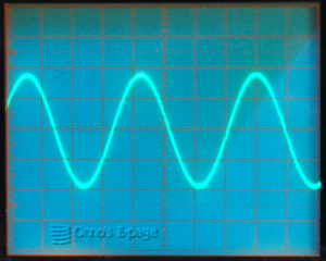
The generator was powered on and started to work.
When switching frequency range,
the signal would disappear, come up abruptly, get distorted and settle to a
nice stable sine wave. That is how the feedback circuit should work.
Checking the voltages it turned out that the power supply voltage was
only 220V instead of 270V.
I replaced the AZ41 and got 275 V.
This is as specified for the GM2317.
The GM2317/01 and later have 300V, but those have a
different power transformer and an EZ80 rectifier valve.
Now the cathode voltage of the EL41 was a bit low.
I saw that the getter mirror on the second EF40 was very thin,
possibly indicating wear.
I replaced it, getting a slightly lower anode voltage.
There was a +1V on its grid so it drew too much current (3&nbps;mA instead of 2).
The anode is DC-coupled to the EL41 so it also offsets the cathode
voltage of the output valve.
The cause was the leaky paper capacitor C11 between first and second stage.
I replaced it by a Philips mylar capacitor.
When turning the output level control, it cracked. It
was dirty inside.
I unmounted it, sprayed a drop of mild contact cleaner inside
and turned it a few times.
Reattached it and the cracking was gone.
I also cleaned the contacts of the range control resistor carrousel.
There was some brownish sticky goo on them, exactly like the
pollution on the contacts of the
GM2885 oscillator I finished
two weeks earlier.
I suspect this is dried-out contact grease Philips originally
had applied.
I cleaned then using isopropyl alcohol first, then ammonia and finally applying
fresh contact grease to the contacts. They should be fine for the next 50 years.
There was a last cosmetic aspect to cure: the rim of the frequency scale
had small rust specks. The scale itself was looking good.
The rust would gradually become worse.
So to stop that, I disassembled the scale and its rim,
sanded the rim, treated it with metal primer and then creamy white paint.
I reattached the rim to the scale
and then the scale to the front of the chassis and the indicator to the tuning capacitor.
Then I resoldered the wires to the BNC-connectors and
reattached the front.
After cleaning, I mounted the knobs and reassembled the cabinet.
This was looking good!
To make the device complete again, I dug up a replacement for the leather
handle on top of the cabinet and attached it, as shown on the top picture.