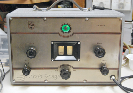
Philips called the GM2885 a Calibrating Oscillator.
It contains a 1MHz crystal oscillator and an auxiliary oscillator.
A tunable amplifier filters the 1 MHz signal to select a single harmonic.
The signals of both oscillators are combined in a mixer stage, producing many
intermodulation products.
The signal level knob controls both signals.
The oscillators can be switched off individually.
Besides the switches and level control, there are two tuning knobs:
- Amplifier filter: 6-22 MHz
- Auxiliary oscillator: 500kHz-1 MHz
This generator was offered in 2025 on the
Dutch Forum on Old Radios.
I had never seen this type before.
It was a bit strange.
It has a grey steel case and a front with aluminium faceplate like
many Philips measuring instruments from 1945-1950, but it looked different.
The faceplate was shiny aluminium with brownish lettering,
just the negative of the usual
black dyed anodized front with shiny lettering.
The black dye on anodised aluminium often fades, this may explain the brownish color.
When I collected it, it was looking quite good.
It was hard to find documentation on the GM2885.
In one of the Philips tube handbooks, part IIIa, and in a book by Philips on
television technology there is only a 3-page description and specification.
On the Radiomuseum.org
site I found a schematic and a parts list, which was useful.
The valve line-up is:
- EF50 main oscillator and AM modulator.
- EBF2 as tunable amplifier.
- ECH21 as auxiliary oscillator and mixer.
- EZ2 as rectifier.
- EM4 as signal indicator.
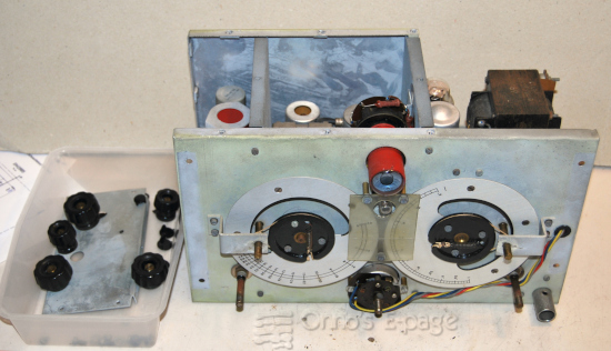
The GM2885 comes in a type of case common to Philips instruments from the 30-ies till 50-ies.
A steel box with the front panel as the lid, the chassis mounted to the front panel.
To open such a case you must remove two or three screws at the back.
Then rest the device on your lap front down and wiggle the case loose
from the front.
Often, the case is a bit stuck and doesn't come off easily.
What was puzzling on the GM2885, was that the two M5 screws on the back were
at the bottom of the backside, not in the middle as with other instruments.
After removing the two screws, the case didn't separate,
somehow it seemed to hinge at the top of the front.
I got the idea to remove the top row of M3 screws holding the faceplate.
That was the solution. Now the case came off easily.
The inside was looking good, although there was some corrosion, especially on
the power transformer.
There was a greenish haze on some of the
steel panels, which means they are probably cadmium-plated.
So I will have to wash my hands carefully.
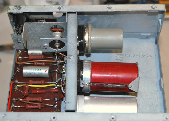
I admired the enclosure of the crystal.
The crystal comes in a metal cylinder, mounted on an Octal base with 6 screws,
looking like a solid piece of laboratory equipment.
It is standing near the EF50N valve and an inductor.
Removing the top, bottom and side panels revealed well-preserved components
underneath and on top of the chassis.
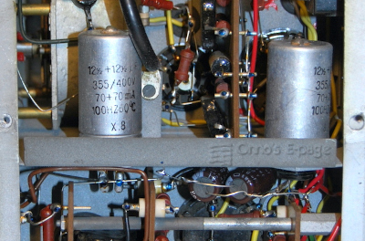
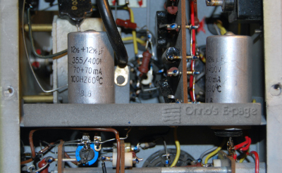
I saw that someone had detached the wires to one section of one of the
power supply electrolytics and had soldered two modern electrolytics
to replace it.
I connected my HV power supply to the + voltage rail to check the total
leakage current of the electrolytic
capacitors and bypass capacitors.
There was a little bit too much leakage current.
It was concerning that the current hardly reduced after a few minutes.
Fortunately, this was caused by the voltage divider for the screen voltage in the output stage.
I detached the leads to the electrolytic capacitors to be able to
test them separately and reform the electrolytics.
During reforming, the good half of the electrolytic went to 0.3 mA
leakage current after reforming at 230V and might improve further.
The other half had a short circuit.
The total leakage current of the bypass capacitors was less than 0.2 mA
at 300V.
The majority of the capacitors in the GM2885 are bituminated mica capacitors,
having good isolation.
The paper capacitors are bituminated paper capacitors in an aluminium cylinder.
It appears that Philips has used exceptionally good paper capacitors for the GM2885.
I didn't trust the electrolytic capacitor I just had reformed partly, because it
was in the same enclosure as one that had shorted.
But I had no suitable replacement.
Of course, I could open the capacitor and hide a modern electrolytic capacitor in it.
Then an idea came up: the negative supply has an identical
2x 12.5μF capacitor with the two sections in parallel.
Maybe I could use that one instead of the shorted electrolytic
and insert a modern replacement in the negative supply.
That would require only a single 22μF replacement electrolytic,
resulting in a less conspicuous repair.
But was it in good shape?
I unsoldered the negative wire to the electrolytic capacitor and started to reform it
cautiously. It took almost four hours, but then it only had a combined leakage current of
0.3 mA, which is neat.
I swapped the two electrolytics, placing the defective capacitor on the
negative supply position to maintain the appearance of the instrument.
I left its negative connection open and soldered a replacement for the negative
supply capacitor to one of its soldering tabs.
Now it was time to try the generator.
I connected it to a variable transformer and set the voltage to 110V.
Nothing happened. I checked. No mains voltage at the power transformer.
It looked like the mains switch was defective.
To get to the mains switch, the front panel had to be removed.
This starts with the control knobs.
Philips used collet knobs on their test equipment.
I realised I was lucky that all of the knobs still had their caps, as these
are often missing.
Well, it turned out that they were all
plastic replacement caps instead of the original bakelite caps with brass springs.
Never mind, at least the knobs had caps.
I loosened the collets and removed the knobs.
Then I removed the four screws securing the front panel to the chassis.
After that, I could detach the mains switch and indeed, the contacts were dirty.
It looked like a layer of dried-out oil.
Maybe the previous owner had used contact cleaner or WD40 and hadn't removed
the residue.
I used contact cleaner to clean the switch and iso-propyl alcohol to remove
the contact cleaner residue. The switch was working.
I reattached the switch to the level control and tried the generator again.
It came to life.
The output signal was unexpectedly strong.
The description of the GM2885 mentions a few 100 mV for the output of
the main oscillator, but this was much more.
Philips didn't specify the output voltage from the auxiliary oscillator
in the scarce documentation I could find.
The auxiliary oscillator signal on the output with the
signal strength control set to max is almost 10V (unloaded).
It looks like this is meant to be.
The auxiliary oscillator and output amplifier are built
like the oscillator and mixer stage of a radio from the era.
The auxiliary oscillator signal is much stronger than the input signal and
in the output signal its residue is still stronger than the
input signal or the mixed components.
In a radio, the oscillator signal residue is filtered out by the IF stages.
Here, there is no such filter.
I checked the circuit diagram but there is no way to reduce the output of the
auxiliary oscillator relatively to the main oscillator.
The signal level control works by varying the bias voltage to the
selective amplifier and the mixer/output stage simultaneously.
Both the EBF2 and ECH21 are variable-μ valves.
The bias voltage to the valves comes from the negative power supply that
delivers -70V. The signal level control
divides this to a variable -40V...0V.
At first, testing the main oscillator was impossible because
the auxiliary oscillator did not switch off.
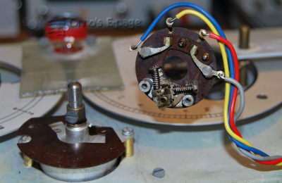
I suspected its on/off switch had the same type of pollution as the mains switch.
I also wanted to tighten the nut that holds this 2-position
rotary switch, because it was loose.
The switch turned to and fro a bit when used, bending the wiring when this happened.
That would cause trouble later on.
So I unsoldered the wires from the switch and the capacitor mounted
to one tab of the switch.
Then I pulled out the switch, cleaned and tested it.
The cause of the loose switch was an extra washer that Philips had placed
between the switch and the chassis.
Near the mounting hole for the switch there is an extra notch for
a protrusion on the switch to
keep it in place when the switch is actuated.
Apparently, Philips wanted to mount the switch in a different angle than originally
designed, so the notch was in the wrong place, why they introduced this washer to make that possible.
The smooth washer does not have much grip and allows the whole switch to turn a bit.
I decided to replace it with a crown washer instead, that catches the protrusion
and grips to the chassis.
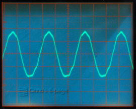
Now I could switch off the aux oscillator and test the main oscillator.
It was working well.
When tuned to an harmonic, the output signal increases as you can see on the
EM4 magic eye. The output was a beautiful sine wave.
It turned out that the 1 MHz oscillator is quite exact.
On my
Monsanto frequency counter,
all harmonics from 6 MHz to 18 MHz were correct within 1 Hz.
Above 18 MHz, the output
signal of the GM2885 was too weak for this counter.
After this, I tested the generator thoroughly, and it seems to work as
designed.
Providing a 10 V
rms 400 Hz AF signal, I tested the
AM modulation. This was working well.
Alas, I could not find a comprehensive manual, so I don't have the
complete instructions on how to use the GM2885.
So I didn't test the mixer output.
Using only a scope, it is not possible to distinguish the various components
of the mixed output signal.
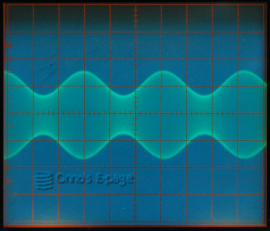
One more observation.
When I was using the auxiliary oscillator on its own and reduced its output to
a lower level,
I noticed that the output waveform was a bit distorted.
At higher signal levels you see the distortion that is to be expected of a valve amplifier
that is overdriven. But the distortion at lower levels was different.
There was an added signal component, that varied with the output frequency but it was not a
fixed harmonic of the oscillator signal, although in the scope image it was stationary so it
was somehow locked to the oscillator signal.
It looked like a spurious oscillation.
This oscillation disappears when the auxiliary oscillator is off.
I cannot find how to remove it.
I tried turning the trimmer capacitor between anode of the
mixer/output amplifier and the oscillator.
This reduced the amount of distortion but did not eliminate it completely.
I still wonder what the original purpose of that trimming capacitor is
and why this parasitic oscillation occurs.
That concluded the tests on the GM2885 generator.
I reassembled it and put it on a shelf.
Maybe I can use it sometime, but I don't know yet what for.
I see why this is a rare instrument: it is only marginally useful.
But still, a nice piece of equipment.
Working well for now.