Philips PM5100 signal generator (1963)

The Philips PM5100 is a basic LF generator from the early sixties. It has 4 ranges from 15Hz to 150kHz and gives an output of up to 10V. I bought it from a collector in 2004. It worked, it landed on a shelf, but in 2026 I found it back and restored it.
The PM5100 is one of the last models of valve based measuring instruments by Philips, dating from the early sixties. It already has a more modern “PM” type number instead of “GM”. The cabinet is a typical Philips professional instrument case from the era, with sheet metal panels with a grey leather-look vinyl coating, grey bezels and grey knobs. It is built very compact. It has no on/off switch, one has to plug it in and out. The frequency control knob makes a 340-degree turn and is sitting on the shaft of the tuning capacitor. Production dates on the components in my specimen are from 1962 and 1963, the valves being from 1963, so it has probably been built in 1963.
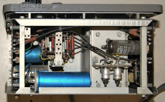
The PM5100 produces a sine wave in 4 ranges, from 15 Hz to 150 kHz. The output voltage is 1mV to 10V. It has two outputs: one with a 600 Ω and one with a 15 Ω impedance. The circuitry has similarities to earlier Philips LF generators GM2317 and GM2315. It is a Wien-bridge RC-generator with incandescent lamps in the negative feedback loop, stabilising the loop gain. The oscillator has a 3-stage amplifier with a cathode follower. An innovation is the active load to the cathode followers, consisting of an extra triode. It has a separate output stage to isolate the oscillator from the load, consisting of another cathode follower with active load. It has no choke in the power supply but only a resistor. The two regulator lamps are Philips 8099-7 type, a special type for this purpose.
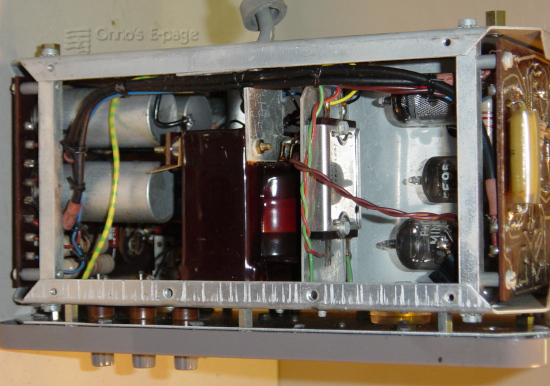
It has more modern tubes than its predecessors:
| EF86 | pentode as pre-amplifier, |
| EF95 | pentode as second amplifier stage, |
| ECC88 | double triode as third stage, |
| E182CC | double triode as output amplifier. |
| two 8099Z | incandescent lamps as regulator |
| B250C75 | selenium bridge rectifier. |
Originally, I didn't plan to buy this generator. It was offered to me by an amateur from whom I bought some other Philips equipment. It was looking well, only the leather of the handle on top was falling apart. When I tried it, it just worked. So it was a usable instrument. But I didn't use it a lot. So it stayed an a shelf, a collector's item.
Getting it to work again
In early 2026, just having fixed two other LF-generators, I found the PM5100 back and decided to try it. Something curious was wrong: the caps covering the collets on the control knobs were all broken. I wondered what had caused that. Later on, the cap in the middle of the tuning dial also broke. It looked like the plastic of the caps had become brittle.
I took the chassis out of the cabinet. On the whole, the condition was good. No rust, only dust. I removed and checked the valves one by one and checked their manufacturing codes and those on the transformer and capacitors.
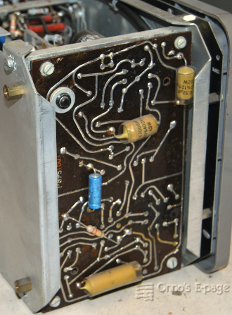
I found a schematic on the NVHR site. There was something odd to the oscillator PCB: several components were mounted on the solder side of the board, there was a 330k resistor on that wasn't shown in the schematic, the screen and anode of the EF95 were interconnected in triode mode. This looked original, there were no traces of repairs. This was different from the schematic, but on Radiomuseum.org there were photographs of other PM5100 with exactly the same modifications. Apparently, there had been an early change in the model, not documented in the scarce documentation that could be found.
I connected my PM5100 to a variac and powered it on slowly. The supply voltage came up but no signal yet. The DC voltage on the cathode followers tended to roughly less than half the supply voltage as the valves warmed. At about 160V, I got a weak signal, distorted. At 200V it was looking better and at 220V it was undistorted.
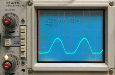
Checking the voltages it turned out that all the bias voltages were in line with the schematic, except for the plate voltage on the EF95 where the circuit had been changed. I played around with the mains voltage and traced the signal through the oscillator. It looked like the lower half of the ECC88 triode, that is used as active load to the cathode follower stage, didn't have enough emission to draw the output low. I tried a used ECC88 from my cache of pulls, but that one was worse. A brand new NOS ECC88 did better: it had less distortion than the original one and it was working good at 200V. I glued the cap of the tuning knob back together and cleaned the cabinet. So now, I had a good working LF generator.
